Harbor Freight Tools 97869 User Manual - Page 9
the Motor Base 5 to the Base Plate
 |
View all Harbor Freight Tools 97869 manuals
Add to My Manuals
Save this manual to your list of manuals |
Page 9 highlights
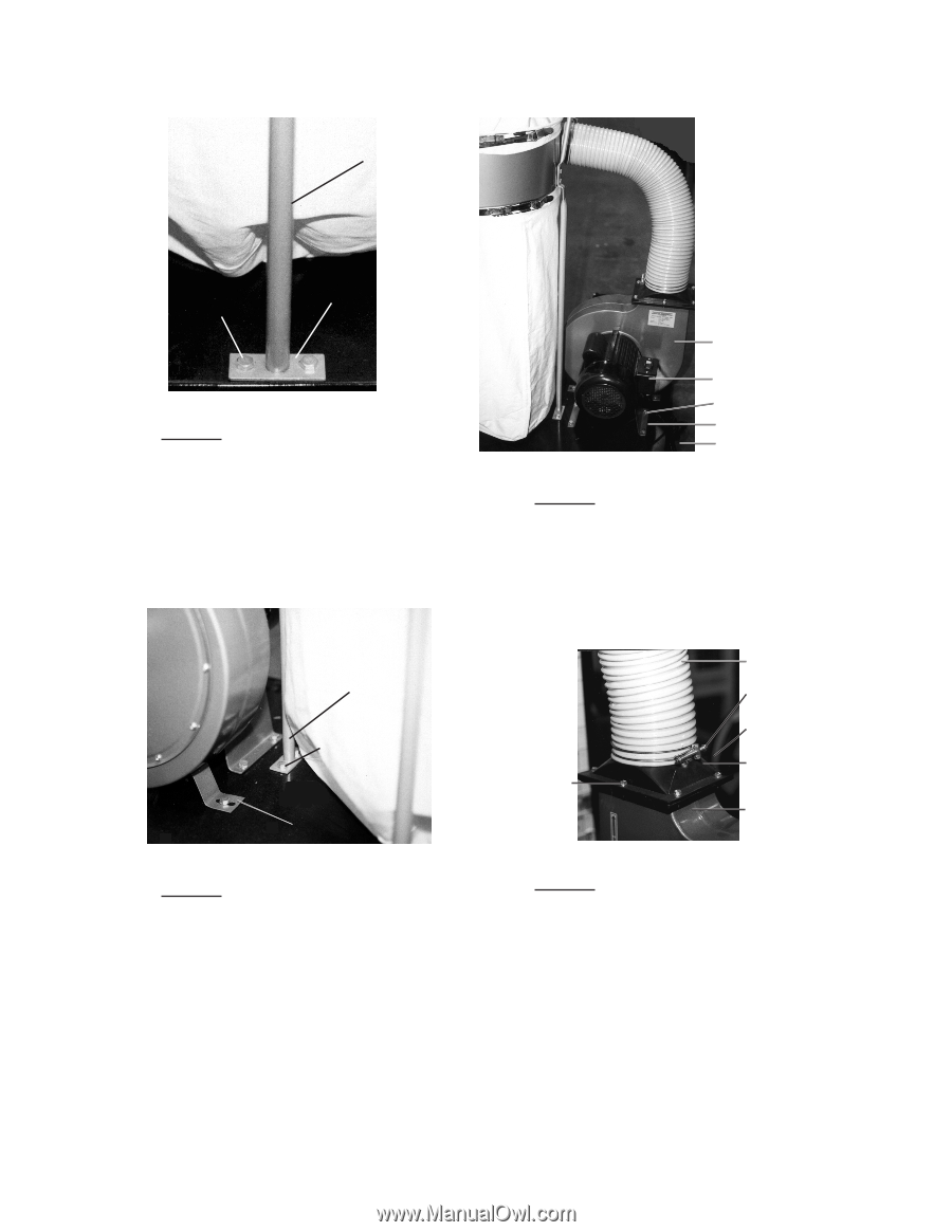
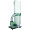
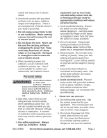
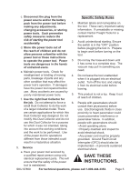
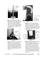
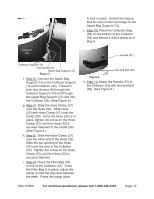
Collector Support (14) Hex Screw (6) Base Plate (3) Figure 1 b. Step 2) Attach the first Collector Support (14) to the Base Plate (3). Line up the Collector Support (14) with holes on edge of the Base Plate (3). Insert Hex Bolt (6) down through Washer (4), Base Plate (3) and secure in place with Nut (2). (See Figure 1.) Motor (8) Collector Support (14) Hex Bolt (6) Motor Base (5) Figure 2 c. Step 3) Attach the second Collector Support (14) through the inside holes near where the Motor Base (5) will be mounted. (See Figure 2.) Insert Hex Bolt (6) down through Washer (4) and Base Plate (3) and secure in place with Nut (2). (See Figure 2.) Fan Housing (38) Figure 3 Motor (8) Hex Screw (6) Motor Base (5) Base Plate (3) d. Step 4) The Fan Housing (38) is attached to the Motor (8) and Motor Base (5) as a single unit. Secure the Motor Base (5) to the Base Plate (3) using six (6) Hex Bolts (6), six (6) Washers (4) and six Nuts (2). (See Figures 2 and 3.) Hose (32) Hose Clamp (31) Hex Screws (15) with Washer (16). Secure with Nuts (2) Figure 4 Outlet (30) Packing (29) Fan Housing (38) e. Step 5) Set the Packing (29) on top of the rectangular opening on the Fan Housing (38) (see Step 4). Set the Outlet (30) on top of the Fan Housing (38) and Packing (29)-see Figure 4. Slide Washer (16) onto Hex Screws (15) and thread into the six (6) holes in the lip of Outlet (30), Fan Housing (38) and Packing (29). Secure in place with Nuts (2). (See Figure 4.) SKU 97869 For technical questions, please call 1-800-444-3353. Page 9
-
 1
1 -
2
-
3
-
 4
4 -
 5
5 -
 6
6 -
 7
7 -
 8
8 -
 9
9 -
 10
10 -
 11
11 -
 12
12 -
 13
13 -
 14
14 -
15
-
16
 |
 |